
Arduino Interactive Lesson 1: Blink an LED
Activity: The Basic Blink Code
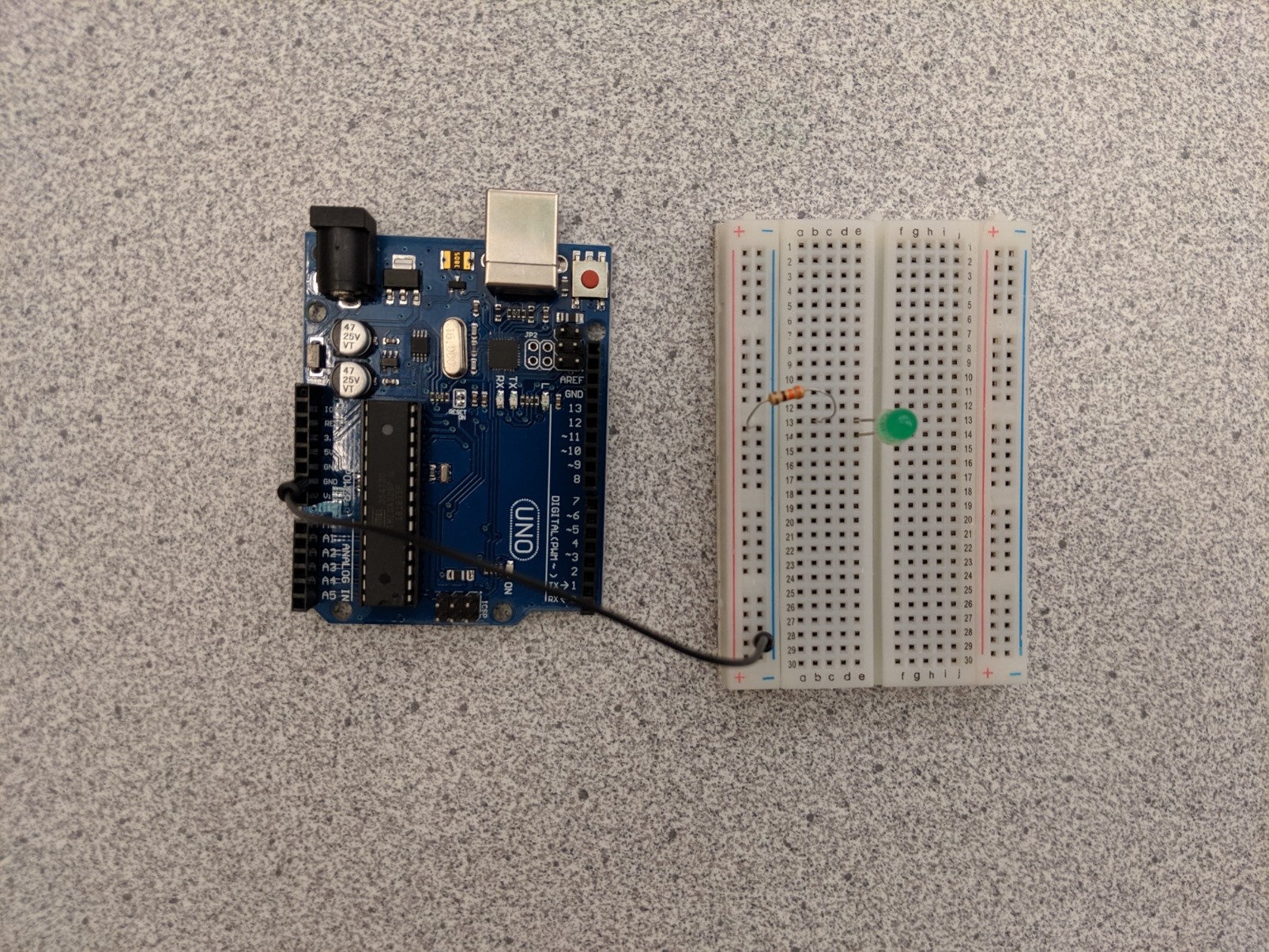
In this activity, you will connect an LED to the Arduino and make it blink. You can always connect an LED to the Arduino in the same way as described below (in step 4, just change the wire from pin 3 to whichever pin you want the LED to be in).
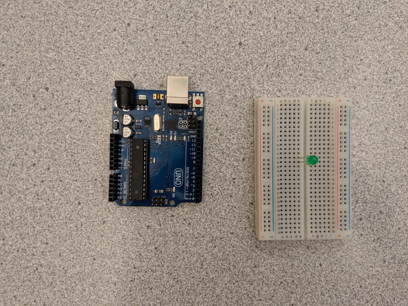
Circuit
Steps
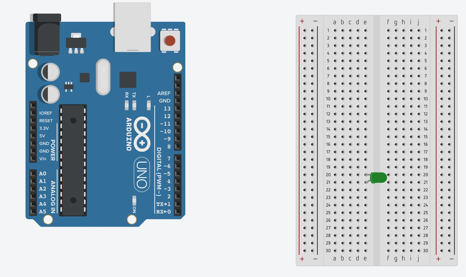
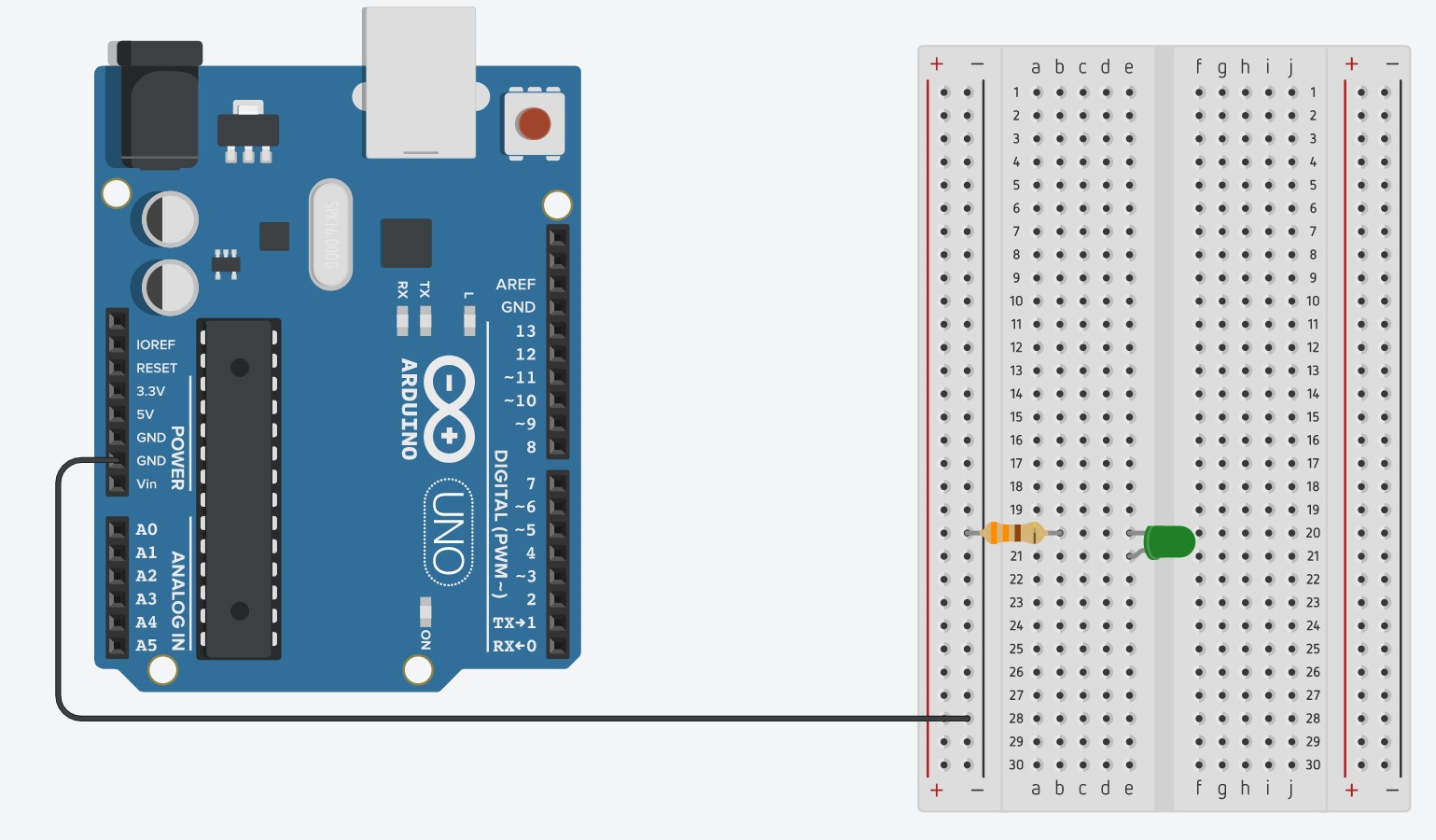
- Put the LED on the breadboard, with the legs in different rows. Remember which end of the LED is the longer side.
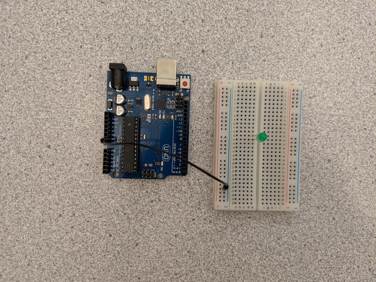
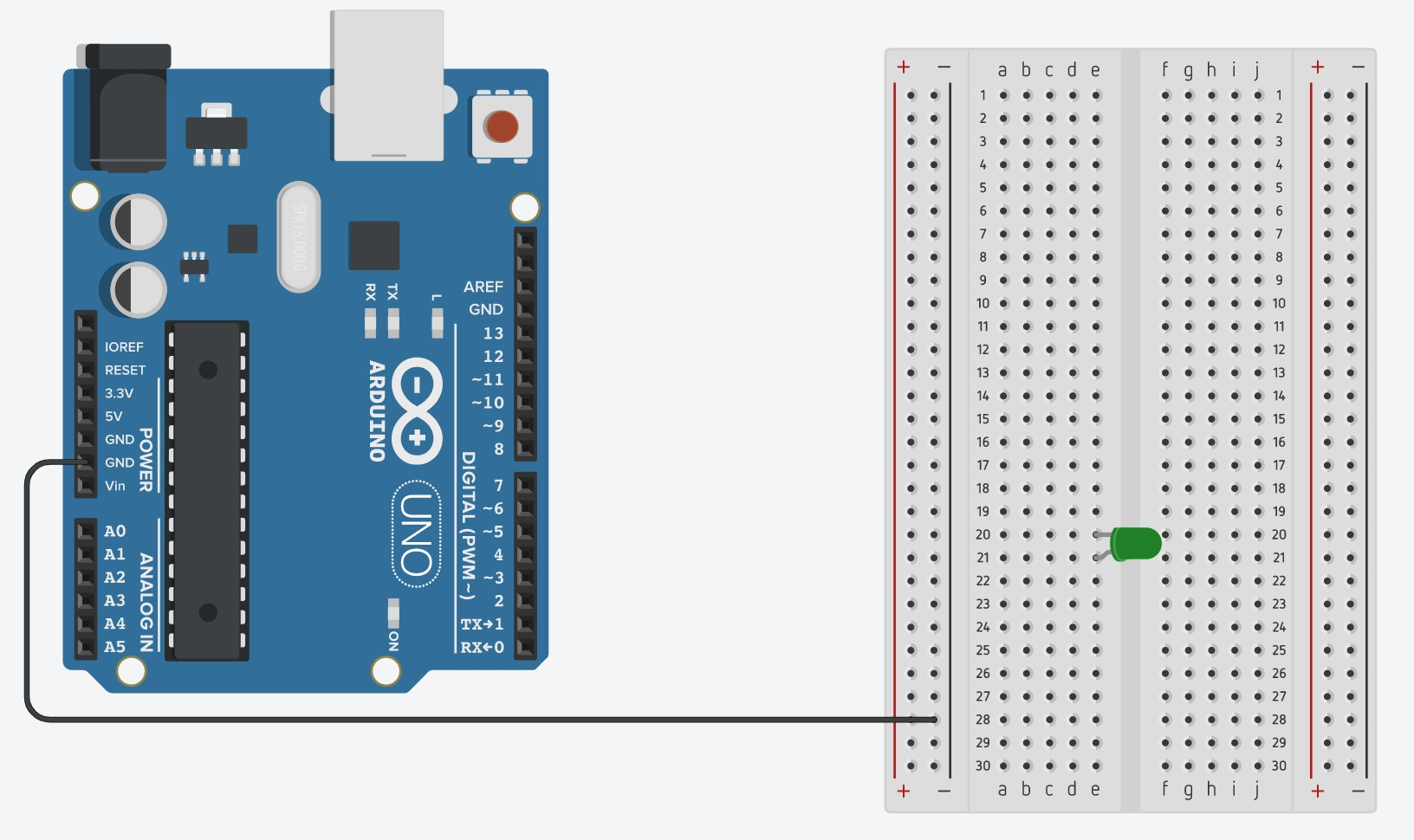
- Attach one end of the black (or cool colored) wire to a GND pin on the Arduino and the other end to the column with the '-' symbol.
- Connect one end of the resistor to the same row as the shorter end of the LED and the other end to the column with the '-' symbol.
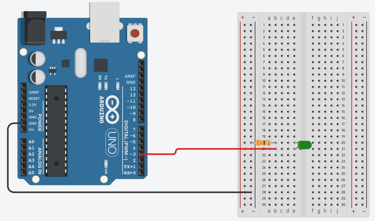
- Connect one end of the other red wire to the same row as the longer end of the LED and the other end to digital pin 3 on the Arduino. Now plug the Arduino into your computer with the connector cable.

Code
To enter the code:
- Open the Arduino IDE or another Arduino code editor on your computer.
- Scroll over “Tools > Board” then click “Arduino Genuino Uno” in the toolbar at the top left.
- Scroll over “Tools > Ports” then click the port that has “Arduino Genuino Uno” in parentheses. (Note: you must do this or you will get an error)
- Enter all of the code line by line into the code editor.
- Click the “upload” button (the arrow pointing to the right).
If your code is still not uploading or working properly, follow the steps in the troubleshooting guide here.
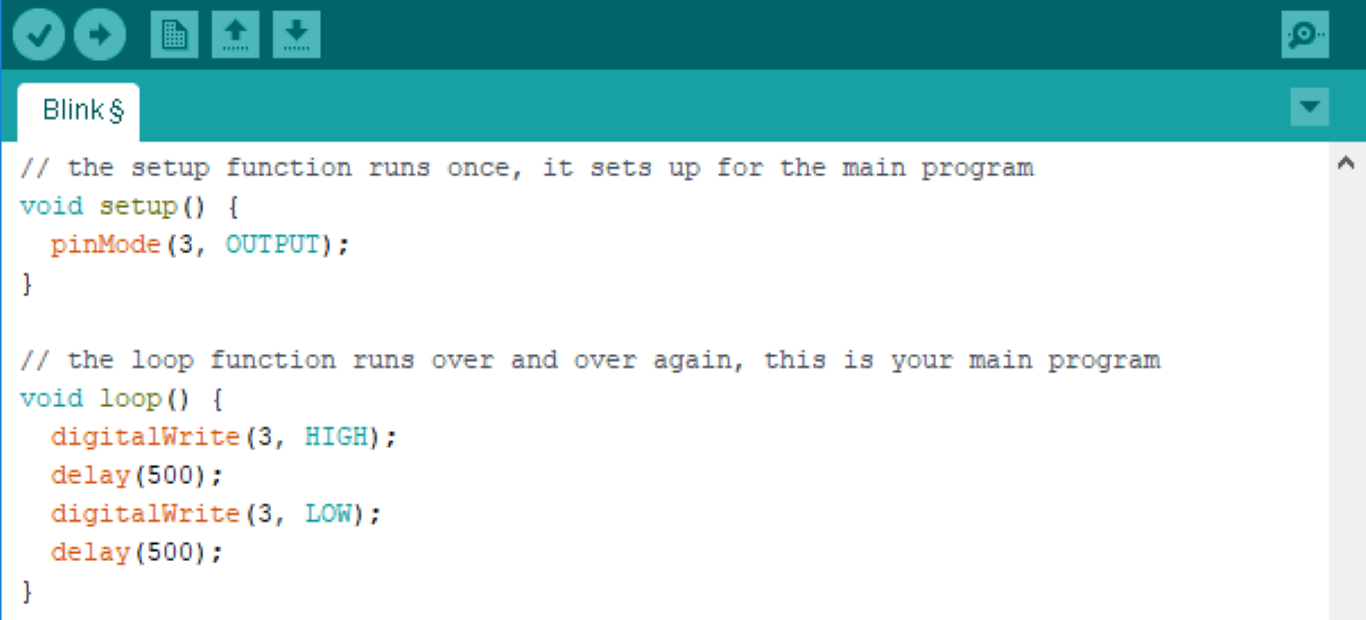
This is what it looks like on the computer screen:
Exploring the Code
Discuss the following questions with your group:
- Change the number in “delay” from 500 to 1000 and reupload the code. What happens?
- How long does it take for the light to turn off after it turns on? Count out 15 blinks, how much time passed (use a stopwatch, or the second hand of a clock). How much time passes during delay(1000)?
- Replace ‘LOW’ with ‘HIGH’ in the second digitalWrite function in the void loop section. What happens? Why do you think this happens?
- Change the OUTPUT in the pinMode function to INPUT. What happened to the LED? Why do you think this is?
- Change the 3 in the pinMode function to 5. What happened to the LED? Why do you think this is? Why is it important that the number is 3 instead of 5? (Hint: Which digital pin is the LED connected to?). Now change the 5 back to a 3.
- Once you know what each line does, leave a comment next to each line of code explaining it (inside the code editor). To leave a comment, write ‘//’ before typing. If you have questions about what each function does, ask your MESA advisor or mentor.
Now let’s add another light. Follow steps 1-4 again in a different spot on the breadboard. This time, in step 4, connect the wire to pin 5 instead of pin 3. Look at the code below, how does the wiring change? What pins are wires connected to?
Code
Exploring the Code
Discuss the following questions with your group:
- Why is the light different for pin 3 and for pin 5? What is the problem with the code? What needs to be added to the setup?
- Fix the code and see what happens with the light.
Challenges:
- Figure out how to wire and code a stoplight with red, green, and yellow LEDs (if you don’t have yellow, you can use a blue LED in its place). Remember that you will need 3 OUTPUTs.
- Have fun making multiple lights blink! Can you make the blink to the beat of one of the songs you like?